精密医疗导管引领者
语言选择:  ∷
∷ 
∷ ∷ 
At a recent industry conference, an executive research and development manager at a major medical device company outlined the company's vision for childbirth treatment via a "vascular superhighway." He says almost any body structure can be accessed through this route. This means there are significant future opportunities for innovative catheter design in minimally invasive treatments.
Catheters have been the foundation of the minimally invasive and minimally invasive treatment revolution. Advances in plastics, metals, electronics, sensors and innovative building technologies have produced unprecedented catheters.
Some of the biggest medical-device companies (Boston Scientific and Guidant, for example) are built on catheter products.
This chapter presents an example study of building a general purpose deflector balloon catheter. In this example, you will see some of the basic components of the balloon catheter, the manufacturing methods of the components, and the basic assembly techniques and equipment. One of the most basic pieces of equipment is a hot air station, which is described in Chapter 5. Common adhesive bonding materials will be described. A glossary of common catheter types is included at the end of this chapter.
The example in this chapter will be a basic steerable catheter, known as a bending catheter, which was a demonstration piece at the annual Beahm Designs medical Device Technology Open House in Santa Clara, California. The device is named after the programme it produces, and is named in a relay from one vendor's booth to another, with onlookers watching.
This demonstration catheter can serve as a valuable introduction to many catheter construction concepts. The demonstration includes thermal bonding of tubing shafts with varying hardness, examples of cable anchorage at the tip and distal tip, and some basic principles for building a steerable catheter. Tools such as hot bellows and tip molds are displayed. Another important method in conduit manufacturing has also been demonstrated: the use of shrink tubes to form heat-bonded joints.
Another feature of the demo article is that many of the projects building this appliance are readily available, and some are even off-the-shelf components. Understanding what can be acquired quickly and cheaply is a key skill for R&D technicians, as it will allow rapid iteration of prototypes, consume minimal scarce and expensive capital, and converge quickly to available solutions.
How is this conduit constructed
The catheter demonstrates some of the inner workings of a simple deflector catheter that would not be obvious to anyone who has not seen the assembled device. The distal catheter shaft is a soft 30 Shore D Pebax material and the proximal shaft is a stiffer 72D Pebax (see Figure 6.1).
One of the most remarkable things about catheter construction, especially when seeing it for the first time, is how much touch and art is involved. Some of the device's features are fairly small and difficult to use correctly the first time. In an R&D environment, it is very helpful to have the assistance of an experienced medical device assembler. This technician can be a valuable resource and work with designers to build the equipment for assembly from the start. Making disposable devices by hand is one thing; However, building 5 or 10 reliable and consistent devices is another issue, while another is scaling up to make hundreds or thousands of devices. Access to skilled and knowledgeable assembler inputs will help engineers design higher quality, reliable, and consistent equipment with good yields and without unnecessary labor. These assemblers often know effective ways to put tools together; engineers may not.
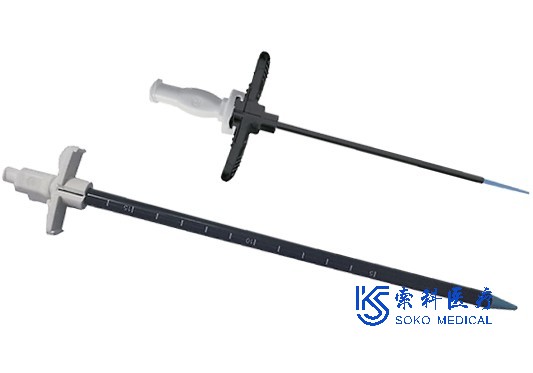
The catheter includes a proximal Luer joint for inflating the balloon and an integrated screw mechanism for actuating a pull wire to deflect the tip portion. In this demonstration device, the feature is to insert the mold into the catheter shaft, which means that the catheter shaft is placed into the injection mold and injection molded around it. This allows the hub to fuse to the conduit shaft without adhesive. This is a useful way to increase production; However, ready-made proximal hubs can be easily bonded to the conduit shaft by thermal bonding, cyanoacrylate or ultraviolet (UV) curing adhesives.
The joint between the Luer joint and the conduit shaft is covered with a heat shrink tube. This is to provide strain relief between the hub and the shaft to prevent the shaft from kinking.
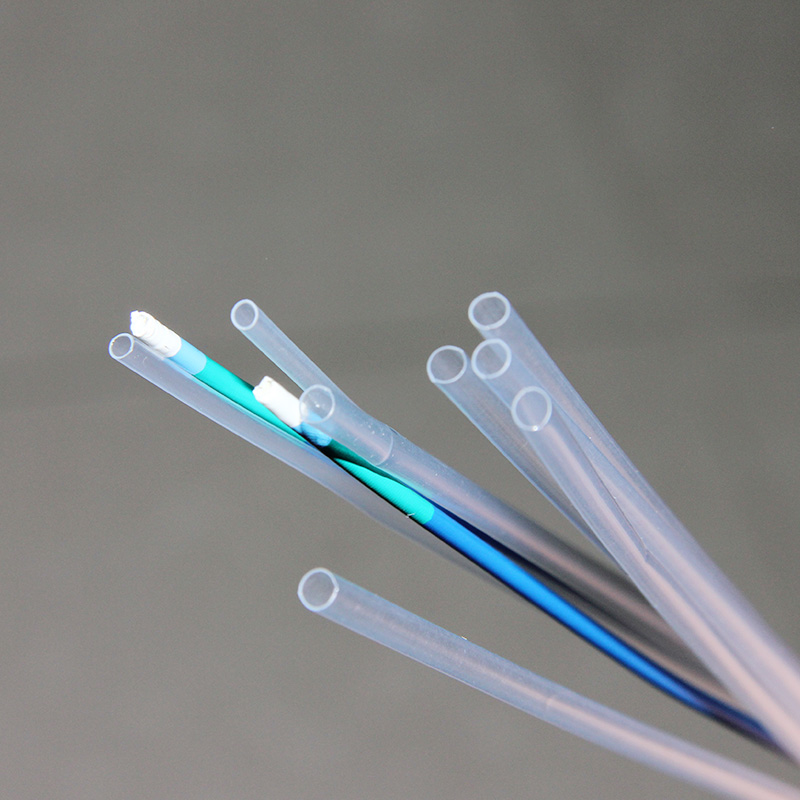
The deflector catheter is operated by having a relatively stiff proximal axis and a soft distal end. The small gauge stainless steel drawwire is extended along the length of the shaft to provide tension to the tip and deflect the conduit. The catheter shaft is a standard two-chamber design with a small chamber for pulling the wire and a larger chamber for passing air to inflate the balloon. Both the softer and harder shafts have the same extrusion profile. Catheter diameter is 8F (8French, 2.7mm or 0.105 in.).
The method shown in the example deflects the tip of the catheter in one direction. Other methods of making a steerable catheter are as follows. If the conduit is to be turned on two or more axes, the extrusion profile will have two linear cavities spaced 180 degrees apart, with the larger cavity located in the center. These wires are fixed at the tip, and to obtain bi-directional steering, the wires are connected to a bell-shaped crank mechanism in the handle (see Figure 6.2). The lever bends the tip in both directions of its deflection. If the wires are placed at the 12:00, 3:00, 6:00, and 9:00 positions of the conduit shaft and are connected to two 90 degree bell crank actuators, they can be extended to allow for four deflection shafts. Gastroscopy and sigmoidoscopy have this type of four-way turning. This type of mechanism makes the catheter more versatile; However, it also makes it bigger, more complex and expensive to build. This may be justified for reusable endoscopes, costing thousands of dollars, but it is difficult to justify in disposable devices. The torsion device, which turns the tip of the tube to make the more complex four-way steering device, is usually just as simple.
An alternative method of making flexible tips on tubing is through bellows (see Figure 6.3). As the name suggests, metal or plastic tubes are cut to create a series of rings, leaving a piece of material behind. The spinal canal is then covered with a flexible elastic sheath. The spine can be made from leftover material in the tube, or it can be a flat piece of metal or a wire spot-welded to a series of rings.
Form the distal tip assembly
The tube end tip assembly is formed by a bullet-shaped glass mold. These molds are described in detail in Chapter 5 using hot air stations and glass molds.
First, cut the wire to the length of the conduit. A piece of small diameter polyethylene (PET) pipe liner is then cut to the length of the distal shaft plus about 0.5 "and slid on the line. The lining will allow the lines to operate freely and provide a bridge between the soft distal shaft and the harder proximal shaft when they are thermally joined together.
To form the anchor for the pull wire, the wire is bent back in the hook 180 degrees, about 0.125 inches (see Figure 6.4). It is then pulled back until the wire hooks into the large cavity of the extrusion tube. Next, the assembly is pushed into a heated mold and heated to the melting temperature of the plastic. This forms the bullet end at the distal end of the catheter and melts the plastic around the wire, holding it in place. Fine stainless steel wire is available from Small Parts, Inc. (Miami Lakes, FL).
Other cutting-edge methods
In this example, a custom glass mold is used to form the catheter tip. This is the best solution given the number of devices that need to be built. However, you may find yourself at your workbench one afternoon or evening, needing to place the tip of an in vitro prototype on a catheter. So what do you do?
One way to tip a die is to make one out of brass or aluminum on a lathe. Drill the metal rod out of the diameter of the conduit and leave a gap. Grind a drill bit (hopefully an old dull bit) into the tip shape you need and grind a cutting edge onto this tool. If you are unable to break the drill, you can do so using the shank end of the drill. Using it as a template tool, carefully drill out the tip shape in the metal rod. Metal rods are machined so that the wall thickness is about 0.125 inches for better heat transfer. Fill the tool with release agent, heat it to transition temperature, insert the catheter until you feel the tip formed, cool the mold, and pull out the (hopefully) acceptable molding tip. One disadvantage compared to glass molds is that you can't see the tip forming and need to do this more by feeling. If you're really short of tools (you don't have a temperature-controlled hot air station), use an adjustable heat gun. With some trial and error and a barbecue thermometer reading up to 500°F, you can calibrate your heat gun and achieve acceptable levels of R&D and proof-of-concept results. Another way to form the tip is to use a plastic tip mold. Teflon rod can be made into tilting mold; However, heating can be difficult.
The tip can also be formed with a piece of silicone tube that is thick enough to extend over the catheter. The tip of the heating tube. Silicone does not melt; However, the plastic inside the tube softens and melts. The tube is operated until the silicone tube is pressed down and the end of the tube is melted. No demoulding is required because the conduit plastic does not stick to the silicone. Heating the far end of the tube causes the plastic to flow more, and the temperature gradient behind the tip creates a taper. If you need to keep the cavity open, use a clean piece of piano wire coated with release agent as the mandrel. (Pam® Non-adhesive cooking spray is only suitable for in vitro prototype or bench testing.) With some practice and the right size silicone tube, you can use this method to form acceptable tapered tips. The final way to form a basic cue is to heat the plastic and (carefully, not burn your fingers) roll it between your thumb and index finger until you get an acceptable tip.
Add the distal tip assembly and the proximal shaft
Once the drawwire and lining have been installed to the distal tip and the tip has been formed, the distal tip assembly is ready to be attached to the conduit shaft. This is done with fluorinated ethylene propylene (FEP) shrink tubes. As a fluoropolymer, FEP tubes have higher heat resistance than Pebax, and the molten tube shaft material does not adhere to them.
Purchase the FEP shrink tube and, when shrunk, shrink to the diameter of the tube shaft. The FEP shrink tube is used as a mold to allow butt welding between the distal and proximal conduit shafts and to pull the shafts together as the tube shrinks longitudinally. As the FEP contracts, it squeezes the melted Pebax ends together to form a joint. The joint is smooth and clean as the shrink tube returns to the diameter of the conduit shaft. Here you can see why the liner is important. Without the liner, the plastic will melt and close the tube cavity, and the tube will be ineffective. The FEP gasket for the drawstring and nylon gasket and bridge is the basic component to make the device work. Once the joint is formed, carefully cut the FEP tube.
Using a nylon liner is actually a shortcut to constructing this particular conduit. This is a way to perform this join operation without special tools. Typically, the conduit cavity remains open, grounded in size, and coated with non-adhesive polytetrafluoroethylene (PTFE) or polyparaxylene during engagement operations with the wire mandrel. Remove these wires after the connection operation, leaving a clean open cavity at the junction. The mandrel acts as the mold core. Another way to form butt joints is to use tubular glass molds instead of FEP shrinkage. Using the glass mold method, the tightly fitting mold is heated and the conduit shaft is pressed into the interior together to form the joint. An advantage of the FEP shrink tube method is that the tube clips evenly onto the tube when welded, resulting in a very smooth and consistent joint.
Perforate the balloon
Usually, a hole is punched in a catheter with a sharp tubular punch. These punches are available from Technical Innovations (Brazoria, TX). Another easy way to drill a hole into a ducted pipe is to use a sharp razor blade to cut a small notch into the pipe. (Drilling is drilling perpendicular to the pipe; Scraping is making an incision in the pipe at a 90 degree Angle.) This is a simple way to drill a hole in a tube while prototyping.
However, none of these methods were used to inflate the balloon by making small pores in the catheter. In this case, the hole is made with a clean, pointed, hot soldering iron tip. This method is a convenient way to quickly and consistently create small, clean holes in the tube without tools.
The proximal Luhr connector is connected.
In this example, a custom Luer joint is inserted into the mold to the proximal end of the conduit. Usually, off-the-shelf Y connectors or some other accessory are glued to the conduit shaft. Standard Luer fittings are available from a number of suppliers including Quosina, Merit, Value Plastics, Brevet, B Braun and several others. Quosina (http:// http://www.quosina.com) is a convenient resource for all types of medical accessories. It comes with a variety of accessories and accessories from multiple manufacturers and has a very reasonable minimum order requirement. Many times, when prototypes are built, the rack does not have the exact diameter Luhr joints required. In such cases, these standard fittings are usually drilled out or modified to meet the current needs.
Another trick for fitting larger tubes into smaller holes: Let's say you have a slightly larger tube and a fitting that you can't or don't want to drill out. If possible, heat the tube until slightly soft and pull carefully, such as toffee. This will stretch the tube and reduce the cross section diameter. If you pull the tube until it stretches and breaks, you now have a conical tube; You can cut it off with a razor blade of the desired diameter. This may not work all the time, but it's a useful technique.
Typically, the adhesive of choice for this application is a UV-curable adhesive (made by Loctite, Inc. Or Dymax, Inc. Manufacturing). Other binders such as cyanoacrylate and epoxy resins can be used, but in this application, UV curing is the most versatile.
To use UV curing adhesive, fittings must be clear to allow UV light to pass through and there must be a UV light source. These lights are expensive (about $1,000 for low-end models), but if you do a lot of conduit prototyping and assembly, they're a very useful accessory. Loctite's newer light-emitting diode (LED-based) curing rods offer an economical alternative to the lamp-base curing rod system. Another economical alternative is the used UV light source originally designed for curing dental composites.
UV adhesives are common and ubiquitous in the manufacture of medical devices. They are used to glue oxygen masks together and hypodermic needles to Ruhr joints. Uv-curable adhesives are also widely used in the electronics industry. There are many types and grades of UV adhesives that can bond almost any material, at least one of which is transparent to allow UV light to pass through. Uv-curable adhesives have excellent gap filling and curing when exposed to UV light. The Dymax and Loctite websites provide excellent information on how to choose the right adhesive to bond material combinations.
It is important to design a UV bonded part so that the UV light fully illuminates the adhesive. If any adhesive is in a shaded area, it will not cure. In addition, even though the material may be transparent to visible light, this does not mean that it is transparent to UV. Most transparent materials
Statement: The articles published in this website are from the Internet, do not represent the views of this site
 微信扫码 关注我们

24小时咨询热线0755-23251960

移动电话191 7359 3045
Copyright © SOKO Medical All Rights Reserved. 地址:Shenzhen,CHINA 粤ICP备2022121184号  粤公网安备 44030402005873号